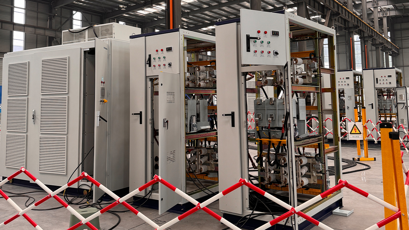


The control system of HV frequency converter includes main control system, electrical primary control system and electrical secondary control system. The structure is simple and compact, which realizes not only the control function of the frequency converter but also the protection function. It mainly includes more than ten kinds of modules, such as HV inlet module, transformer and power unit module, controller module, voltage and current detection module, power supply module, fan cooling module, digital input module, digital output module, analog control module, HMI and communication module.
The data signals transmission between PWM boards in the controller and power units are realized through fibers, and each fiber board controls the all units in one phase. The PWM board periodically sends control signals and working modes to the units. The units can receive the commands and status signals through fiber, and send fault signals to PWM board when faults happen.
The digital board receives the logic control signal from the CPU board, and then controls the open and close of the contactors in control cabinet and bypass cabinet through the digital output adapter board. The status indication signal of frequency converter is sent by digital board. Remote control signal, contactor feedback signal, fault feedback and other digital signals are transmitted to the digital board through the adapter board, isolated and processed by the CPU board.
The key control of the controller is completed within the CPU board, which adopts DSP processor to complete all functions of the converter control; to collect control signals of digital board, analog board and communication board; to generate a three-phase voltage command and logic control command of pulse width modulation by perform calculations.
The analog module collects the analog signals of input voltage, output voltage, input current, output current and sensor detection, and transfers the analog signal conversion board into the analog board for analog signal isolation and filtering. The converted signals are transmitted to the CPU board, used for the control and protection of the frequency converter, and displayed on the touch screen. At the same time, 4 analog signals are output, which is convenient for displaying the operation data in the background.
The system supports remote communication control, and the converter can be operated and monitored by the host computer or backstage computer.
Stay connected
Be the first to know about our new product launches, latest blog posts and more.
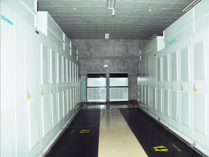
The production base of Schorch Electric Co., Ltd. is located in Suining City, Sichuan Province. It adopts the advanced technologies and manufacturing techniques of Europe. The production technologies are advanced, stable and reliable.
Any question or request?
Click below, we’ll be happy to assist. Contact us