

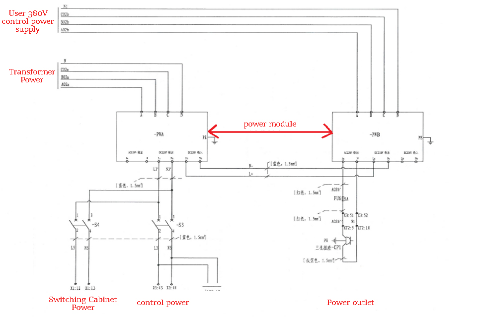
The AC380V power supply provided by the user is divided into two paths through the switch, and one is connected to the rectifier power module PWA through the main power switch; And the other is connected with the low-voltage charging module. After connected to the charging resistor and the charging contactor, the incoming switch is connected to the tertiary winding of the transformer to form a low-voltage charging circuit.
When the KC control system issues the charging command, it controls the charging contactor to close, and the power of AC380V passes through the charging resistor to the tertiary winding of the transformer, so that the primary side of the transformer induces 6KV or 10KV high voltage, and at the same time, all secondary windings of the transformer generate supply power of 690V voltage to the power unit. When the charging of system reaches the set value, KC control system controls the charging contactor to open and close, and the high-voltage input contactor to close. And then the frequency converter is powered by the high-voltage power supply.
After the charging of the system, the power contactors of the system and incoming power supply are closed, and the AC380V circuit of the tertiary winding of the transformer is electrified and connected to the rectifier power supply module PWB through the switch S1a. It is connected to the control circuit of the temperature controller through switch S5 and also responsible for the power supply of the fan at the bottom of the transformer at the same time. The other path supplies power to the fan circuit through switch S2 and contactor.

The cores of the module are AC/DC power supply, and PWA and PWB power supply system. The structures of the rectifier power supplies of PWA and PWB are the same structure, with inputs terminals connected with the control power supply and the tertiary winding of the transformer respectively; and outputs terminals connected in parallel.
The input AC in the rectified power supply passes through the input filter, which filters out the input harmonics. The rectifier output is connected to the isolation transformer, which plays an isolation role. The AC power passing through the isolation transformer is added to the rectifier switching circuit, to change the AC power into pulsating DC power, which is then filtered by capacitor filter and output DC filter.
The two rectifier power supply modules automatically switch the power supply based on the principle of diode single-phase conduction, to convert and output stable DC220V voltage.
Part of the power supply adopts dual-circuit power supply system, that is, the AC380V power supply provided by the user and the AC380V power supply changed from the tertiary side of the transformer. The main function of the dual-circuit power supply is to ensure that the AC380V power supply provided by the user is unexpectedly cut off during the normal operation of the frequency converter, and the system can still run normally without causing the power failure of the whole circuit and the power failure of the control system when the high voltage power is not cut off.
The frequency conversion system is powered by AC supply, and the DC220V power generated by the rectifier module is used for contactor, switching power supply and external equipment respectively. There are three switching power supplies PW1, PW2 and PW3 in the power module, with input of DC220V power.
Stay connected
Be the first to know about our new product launches, latest blog posts and more.
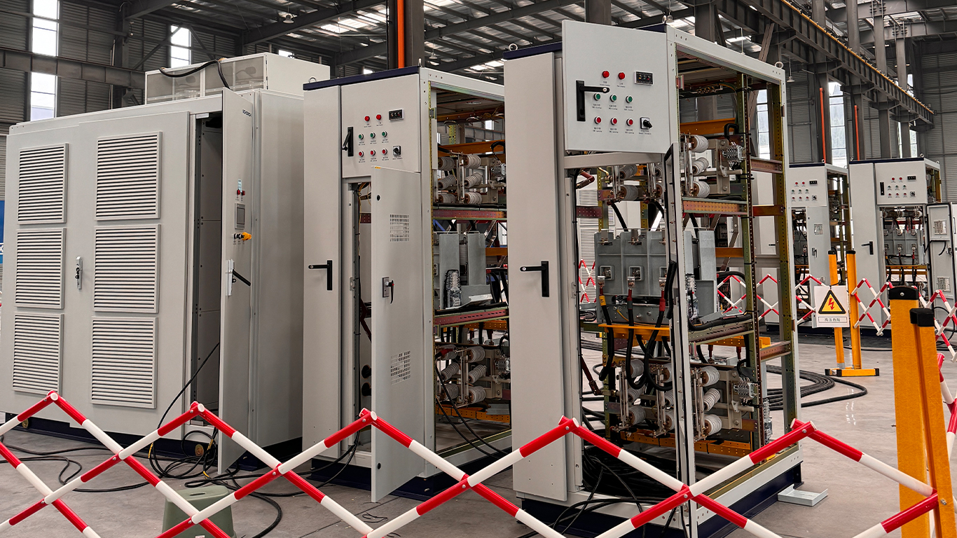
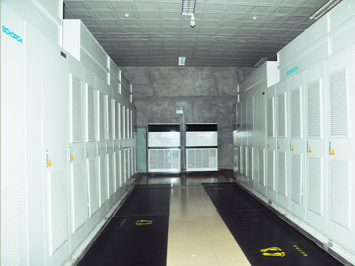
The production base of Schorch Electric Co., Ltd. is located in Suining City, Sichuan Province. It adopts the advanced technologies and manufacturing techniques of Europe. The production technologies are advanced, stable and reliable.
Any question or request?
Click below, we’ll be happy to assist. Contact us